


We would like to introduce you a special limited edition of ten DC/DS-24 transmitters, which was created for the 75th anniversary of the end of World War II. Unfortunately, the release of this series last year was significantly affected by a global pandemic, which also affected our plans. The limited edition is intended for end customers, collectors and fans of JETI and is created in the spirit of flying legends of World War II. Each transmitter has original design, which was artistically painted directly on the transmitter (Airbrush).
You can find more information and photos on our Facebook profile JETI Model.

1. REX Assist v1.19 (03/2021)
Airplane pitch with Assist enabled is no longer affected by acceleration (Horizon mode).
2. MVario2 FAI F5J v2.05 (03/2021)
Supports new sensor revision.

-Time interval of the RX alarm was modified to 2s.
-Extension the compatibility for Futaba R7008SB (S.BUS)
The update can be done by the Jeti Studio.
SBEC 40

| Weight [g] | 100 |
| Dimensions [mm] | 80 x 36 x 25 |
| Sustained current [A] | 18 (3S LiXXX) |
| Telemetry | No |
| Operational temperature [°C] | -20 ... 85 |
| Recommended input voltage [V] | 8 ... 51 |
| Output voltage [V] | 5.0 / 5.5 / 6.0 / 7.0 / 8.0 |
| Idle current [µA] | 85 (10S LiXXX) |
| Number of battery inputs | 1 |
| Input voltage max. [V] | 51 |
| Peak current (max 5s) [A] | 40 |
Files for download
Manuals - SBEC 40
The switching voltage regulator SBEC is supposed to function as a current supply for receivers and servos. It enables to use a wide range of input voltages from 3S up to 12S Li-XX cells. Setup of the output voltage between 5 and 8V is accomplished by a shorting plug jumper. This implies that the SBEC is also prepared for use with new „higher“ voltage servos. The SBEC is suitable for medium and larger model due to its maximum current of 40A.
The output voltage is adjusted with the aid of a shorting plug (jumper) in steps of 5.0V, 5.5V, 6.0V, 7.0V and 8.0V. An important condition of keeping correct output voltage in connection with the jumper position is a sufficiently high supply voltage. The supply voltage of the battery must by all means be higher than the required output voltage. We recommend a minimum difference of at least 2V above the output voltage. Otherwise the output voltage would decrease under load conditions. The switched-on condition of the regulator and the information about the presence of voltage at its output are signaled by a shining green LED.
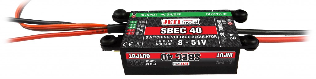 |
Table showing dependence of sustained current loads on input voltages:
|
Number of Lixx Cells |
3 |
4 |
5 |
6 |
7 |
8 |
9 |
10 |
11 |
12 |
|
Sustained Output-Current* [A] |
18 |
17.5 |
17 |
16.5 |
16 |
15.5 |
15 |
14.5 |
14 |
13.5 |
* Sustained current values are valid only for operating conditions with sufficient cooling airflow


