 |
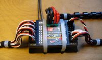 |
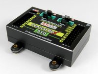
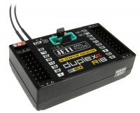
Casing seems to be very robust and its stiffness is increased by 5 screws. All inputs and outputs are vertical to the board thus the servo cables are secured against unwanted removal. The receiver does not heat during usage thus you needn’t leave a gap between the receiver and the pad or do anything else to cool it down. The receiver and servos can be supplied classically via servo connectors but MPX connector is designed for power supply. Its three pins for plus and three pins for minus are designed sufficiently for electric current and safeness. The connector is equipped with arming pin against unwanted removal of supply cable.
Two tested antennas were 38 cm long including active end. The active end of antenna is equipped with protective isolation against damage of input network caused by static electricity.
Besides the connector „Ext.“, designed for connecting Jetibox, telemetric sensor or expander, there are 18 golden-coated connectors of output channels. Outputs 17 and 18 are also marked as SAT1 and SAT2. They are designed for connecting satellites or parallel receivers. R18 receiver is described as 18 channel receiver but if we connect satellite or other receiver to the output 18 or 17 then we will have only 16 or 17 output channels. R14 has SAT1 and SAT2 independent so if we connect anything to them, we still will have 14 output channels.
 |
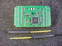 |
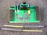
The most important part – the receiver itself – consists of one double-sided stepped multiply board. Receiver is stepped with new input networks that should be more resistant and more sensitive. Both antennas are not connected with the easier process (i.e. connectors) but they are truly soldered. Power supply of receiver and servos is from the common MPX connector but it is internally separated. One branch, designed for supplying servos, leads directly from MPX connector to the outputs. Its current loading is limited only by feasibility of golden-coated output connectors because whole surface of top and bottom of the board makes plus and minus supplying pole. Second supplying branch is separated and stabilized branch line for supplying network of the receiver. This branch has its own protection against spike and possible interference from supply cables. We can mention another unusual protection. As we can see in the picture (back side of the receiver), every signal pin of output connectors has its own protection against possible interference from damaged or low-quality servo, regulator or other interference from servo outputs. Level of servo pulses is regular, 3.3 V.
The receiver can be run separately i.e. without satellite or parallel receivers. However its maximal potential and maximal level of safeness appears when we use it with one or two satellite receivers. These small satellite receivers operate as full-featured second reserve receivers. At the 2.4 GHz frequency, antenna can be easily blocked out for a while and the signal can be lost. Also antenna that is directed with its axis to the transmitter has minimal function. If there are larger areas of carbon or metal on the plane, you cannot be sure, even if you put there two antennas, that at least one antenna will be covered by signal all the time. However if we have four receiving antennas and we place them properly, we have secured that we will have signal at every position of the plane.
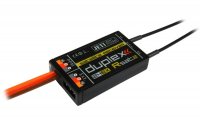
Satellite receiver Rsat is equipped with the same kind of antennas as the main receiver R18. Supply coaxial cables are sufficiently long – 17cm. Cable for connecting the main receiver is common triple-core 30cm long servo cable. Satellite receiver is also supplied via this cable from main receiver.
As the manufacturer says, there should not be any problem with connecting cable „satellite-receiver“ that is 2 metres long. Thus it is not a problem even at really large models to place satellite receiver to the end of a wing or to the top of a rudder.
 |
If anybody is interested in how main and reserve receivers communicate between each other then it is very simple. If main receiver does not detect proper signal from its own input networks, it takes the signal from satellites. Once the signal reappears, it takes the signal from its inputs and antennas again. Main receiver and reserve satellite receiver communicate by common PPM signal and this line allows, because main receiver can select not only input but also output of PPM signal, many various configurations.
1. The simplest option: Duplex Tx in the transmitter, one R18 receiver in the plane
2. Standard, recommended by manufacturer: : Duplex Tx in the transmitter, one R18 receiver in the plane + one (or two) back-up satellite Rsat receivers
3. „Heavy configuration“: Two Duplex Tx in the transmitter, two receivers R18 connected by PPM line in the plane, Both receivers can have separated or common power supply, both are run in „normal mode“. They are both independent. Route „transmitter and its antenna – receiver – accumulator – servos“ is fully doubled and independent. However, when one receiver does not get the signal, it automatically takes it from the second receiver.
4. „Heavy megahertz configuration“: There remains the original transmitting module in the transmitter + Duplex transmitting module, we take PPM signal from megahertz receiver and we connect it (also with power supply) to the input SAT1 of the receiver Duplex R18. If the R18 receiver does not get proper signal from its transmitting module then it takes the signal from megahertz receiver.
You will certainly find more possible configurations. Do not please take consider this as manual but take it as an example of few possible configurations.
Very sophisticated programming of the R18 receiver and satellite Rsat has its origin in well-established software of Duplex R8 but a couple of new functions were added.
Reserve satellite receiver got only one new function: PPM output mode. You can choose either „direct“ or „computed“. If you choose „direct“, the PPM signal is not modified and it is directly sent to input of the main receiver Duplex R18. A possibility of setting is surely also important. Imagine how scared you could be by the failure of signal in the main receiver and switching over to a satellite, where you have left active mix or differently set the order of channels in the porgram of the satellite receiver.
Duplex R18 got not only necessary but also very useful function. Output 18/Sat1 is designed for connecting the first reserve satellite receiver. If you choose „PPM output“ then the receiver will receive and monitor signal from reserve receiver at this input. You can activate optional warning sound for controlling the right signal at this input. If there is not proper PPM signal from satellite at the input 18, you will hear warning sound every 15 seconds. This function is very important and it is the only way how to check if the satellite receiver works properly. You can select the same function at the output 17 but here the function is extended by the option of selecting „PPM output“. This connector can act as regular servo output 17 or as a connector for connecting second satellite receiver (PPM input) or as PPM signal output (PPM output).
This output PPM signal can be used for example for connecting another R14 or R18 receiver. With these two functions, we can theoretically connect as much receivers and transmitting modules to one model as we want. In my opinion, having more than two transmitting modules and two receivers (in this case a receiver and a satellite) will not increase the safety but it only increases complicacy.
Another new and interesting function is „Output trim“. Even before you could have set maximal deflection for every servo. Now you can in addition set also mean neutral position. This allows full „mechanical synchronisation“ of servos.
The final new function is „Output Group“ – electronical synchronisation. Every input channel can be now put to one out of 8 groups marked A,B,C….H. Servos at one group get command at the same time – they start and break at once. Servos at one group will move in synchronism in time, in a size of the move, and also in the position of neutral. This is very useful for models where one controlling area is controlled by more servos (e.g. every half of the elevator has its own servo, or for helicopters).
Also opposite application is possible. With the speed and the torque of servos, even their current consumption is increasing. It is extremly high at start / break of the servo, and it causes large and dangerous voltage peaks. By means of "Output Group" function we can, on the contrary, divide servos with no need of synchronized movement into different groups, and thus ensure that they do not start at the same time. For example if we have a gear doors controlled by a servo, it doesn´t matter if one door is closed a few thousandths of a second earlier than the other one. It is even more appropriate and safer if the servos do not start at one moment.
I was also interested in thermal endurance of the receiver. Manufacturer indicates 85 oC. I have tested one receiver. I put it without casing to a small air-conditioned room for half an hour. Air humidity was not changed, the temperature was set at 85 oC with 10 minutes´progressive run-up. Silicon extension cord of the servo (HS-5945MG) and accumulator (4x NiCd) were outside of the room so they stayed cool. There had been set „servos test“ program during the whole test. I did not noticed any problem or malfunction..
Current consumption was 45mA (receivers) and 38mA (satellites) with 5-cell NiCd. Electric tension allowed by manufacturer is between 3.2 – 8.4V. Often discussed topic is sensitivity to voltage reduction of 2.4GHz systems. Servos (HS-5945MG, HS-645MG, GWSpico) were supplied by 4-cell NiCd, receivers by laboratory power supply, and the tension was measured at the pins of the receivers. When the tension was 3 V everything worked with no problems. One receiver stopped to operate at 2.96 V and the second at 2.94 V. Both satellite receivers worked well to 2.85 V.
It will never be possible to reach 100% safety and reliability in RC models, but we can approach to it. Generally, equipment working in this frequency increase the safety. R14, R18 and Rsat bring the safety to new dimension either by the construction or the option to double transmitting and receiving feature.
Ing. M. Pastyřík


