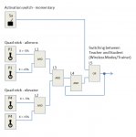
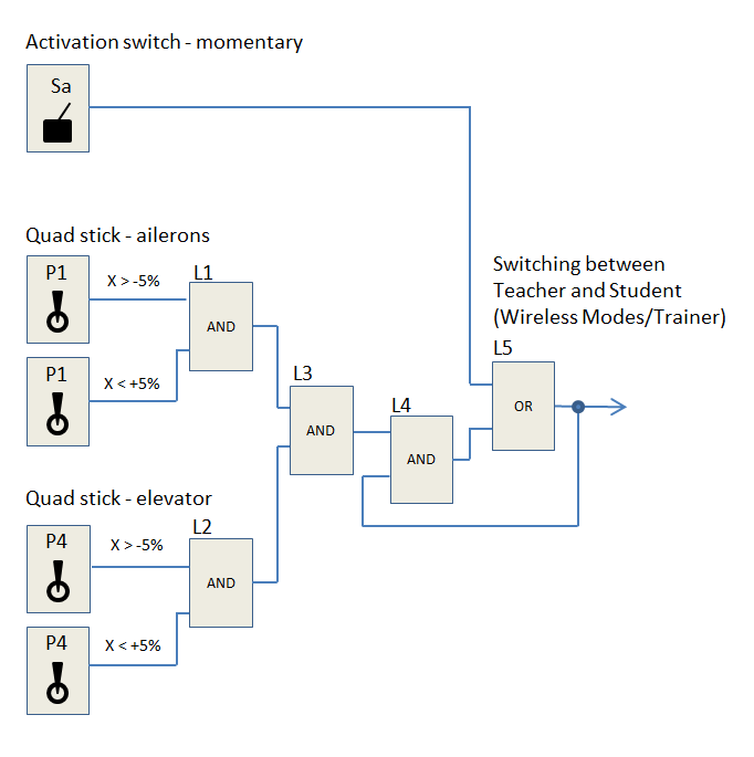
Schematic diagram of logical switches
The resulting function
- The Teacher and the Student transmitters are paired in the wireless mode of Teacher–Student.
- The Teacher moves the control sticks to the middle position and pushes the momentary switch (Sa in this case). This passes the control to the Student transmitter.
- If the Teacher wants to take over the model control again, the Teacher simply moves the ailerons or elevator stick. Thus the Teacher controls the model again.
- The control is given back to the Student by putting the quad sticks to the middle position again and pushing the momentary switch.
Step by step setup
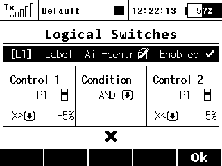 |
1) The L1 switch is active in the middle position of P1 control (ailerons). |
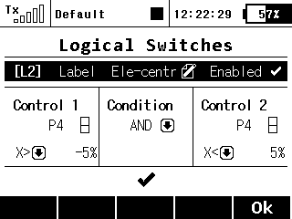 |
2) The L2 switch is active in the middle position of P4 control (elevator). |
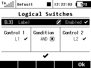 |
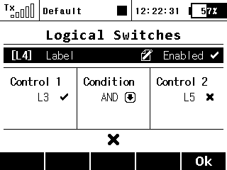
3) If you want to pass the control on to the Student, the P1 and P4 controls must be in the middle position. This is carried out by connecting logical switches L1 and L2. |
 |
4) Feedback application. |
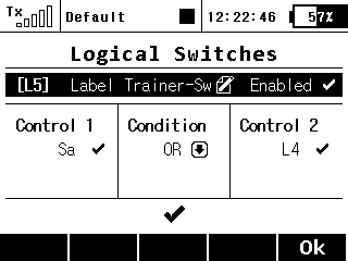 |
5) Activation using Sa control. After pushing this control, the Student takes over the control. |
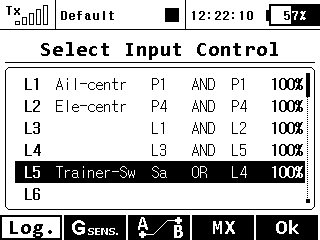 |
6) The summary of generated logical switches. |
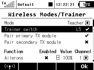 |
7) Assigning the final control L5 for switching control between Teacher and Student. |


